Reviewing Hydraulic Connections on a Final Drive
Feb 9th 2020
There can be up to five hydraulic connections to your final drive. Do you know what each one is for? This blog post will help you review that information whether you have a mini-excavator, skid steer, or compact track loader.
Final Drive Flow and Return Lines
A typical final drive motor will have 2, 3, 4, or 5 hydraulic connections. A minimum of two hydraulic ports (and lines) will always be present. These lines are known as the flow and return lines, and they will connect to the flow and return ports on your final drive. These lines are what provides power to the motor, and if they are connected in reverse then you will probably see your final drive running in the wrong direction.
The flow and return lines are usually the two largest diameter lines and are a matching pair of steel pipes or rubber hoses. They are also associated with the largest ports on the travel motor.
Final Drive Case Drain Lines
If more than two lines are present, one of the lines will be a case drain line. All piston-type hydraulic motors are going to leak oil from the rotator group. This is a good type of leak: it is used to lubricate the piston shoes, the swash or thrust plate, and the area between the cylinder block and the valve plate. This oil must be returned to the hydraulic tank under minimal pressure. That is the purpose of the case drain line, which runs from the travel motor to the hydraulic tank. Note that this is a low pressure line and is where you will find the case drain filter, which we have discussed in other blog posts.
Note that if there are only three lines, the smallest one will most certainly be the case drain line. Some travel motors actually have two case drain ports present and they are interconnected, meaning that either one can be used. You always want to use the highest case drain port on the unit due to air circulation of the motor: if you don’t use the highest one, you will have cavitation in the motor because the air cannot escape.
Final Drive Speed Line
If your motor is a two-speed model, then there will be two-speed line in addition to the flow and return lines. This controls the speed of the travel motor. It will be the smallest line of all. Hydraulic fluid only flows through the lines when the machine is set to high speed mode. The speed line connects to the speed port, which is going to be the smallest port and may be on the back side of the travel motor.
Final Drive Brake Line
A brake line may also be present. It may be on the side or behind the main housing. This is one of the smaller pipes, and should only be pressurized when the travel lever is in operation.
Examples
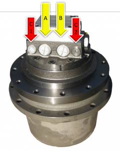
This final drive has two ports for the flow and return lines (marked A and B) and two case drain ports (marked C1 and C2).
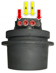
And here we have yet another model of final drive with the flow and return ports in the center and the case drain ports on either side. In this one you can clearly see that the case drain ports require smaller lines than the flow and return ports.
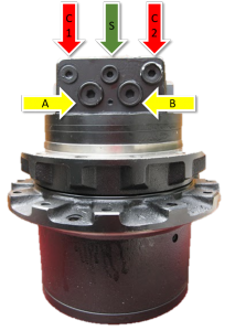
For our final example, this travel motor includes the two-speed port (highlighted with a green arrow and labeled S). You will notice the two-speed port is much smaller than the flow and return ports and the case drain line. Remember — the case drain port is usually the second largest port (after the flow and return ports).
Conclusion
With up to five different lines connecting to your final drive, it can get confusing when it comes to figuring out which line connects to what port. We hope this review helps!


